The antenna shown in Fig. 1 is a four elements Long Yagi, installed since last year at 12 meters above the ground.
The boom is 5.90 meters long and the feeding system is a common Gamma Match.
After many trials on my computer with Y.O. (Yagi Optimizer), I found that the best compromise between Gain, F/B, Impedance and Efficiency, is a long boom with few elements.
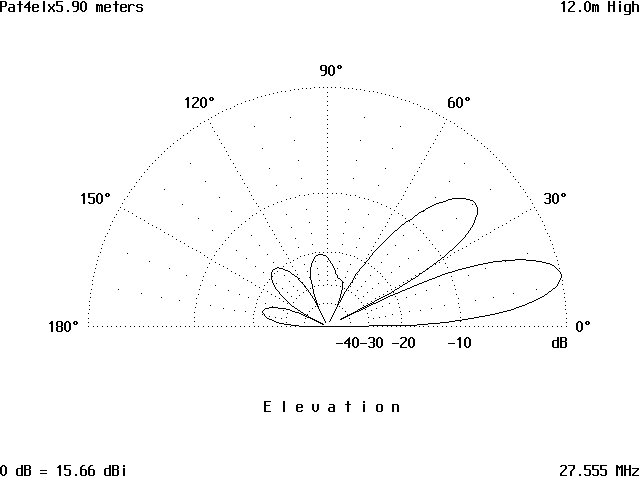
Moreover , after many years of operations on 27 Mhz, I recognize that the Gain is very important but also the horizontal and vertical beamwidth are essential for an extra performance. To achieve maximum gain, I tuned my antenna at 27.555 Mhz with a passband of only 300 Khz. from the centre band. Also this feature (very sharp response) help me very much to reduce drasticly the splatters from local stations on AM or FM .
Many operators contacted in the last months ask me to give more details of my antenna system: I think Internet is the best way to reach all of them and others antenna's fans.
The boom is 5.90 meters long and the feeding system is a common Gamma Match.
After many trials on my computer with Y.O. (Yagi Optimizer), I found that the best compromise between Gain, F/B, Impedance and Efficiency, is a long boom with few elements.
Moreover , after many years of operations on 27 Mhz, I recognize that the Gain is very important but also the horizontal and vertical beamwidth are essential for an extra performance. To achieve maximum gain, I tuned my antenna at 27.555 Mhz with a passband of only 300 Khz. from the centre band. Also this feature (very sharp response) help me very much to reduce drasticly the splatters from local stations on AM or FM .
Many operators contacted in the last months ask me to give more details of my antenna system: I think Internet is the best way to reach all of them and others antenna's fans.
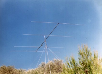
Fig.1
| Boom | 5900 long (0.54 l.w.) |
| Reflector | 2708.8 " |
| Radiator | 2600.0 " |
| Director 1 | 2504.7 " |
| Director 2 | 2424.2 " |
| Reflector spacing | 0 mm |
| Refl./Radiator | 1044.5 mm |
| Refl./Direcetor 1 | 3126.0 mm |
| Refl./director 2 | 5900.0 mm. |
Since the element lenght is depending of the diameter of pipe used, I will list for each half element the lenght and the diameter for all sections; the first 2 sections are the same for all the four elements:
| Section 1 | 1000 mm long by 20 mm. diam. |
| Section 2 | 900 mm long by 16 mm. diam |
The last section is variable as below:
| Reflector: | 887 mm. by 12 mm. diam |
| Radiator: | 774 “ “ “ “ “ |
| Director 1 | 674 " " " " " |
| Director 2 | 589 " " " " " |
| GAIN | 15.66 Dbi |
| F/B | 22.01 Db. |
| Imp. | 15.8 -J0.5 |
| SWR | < 1:1.5 from 27.3 to 27.8 MHz |
| Vert.beamwidth | < 14° |
At 27.555 (band centre) the SWR is 1:1.0
The antenna was tuned at about 3 meters above the ground and after a couple of adjustments of Gamma Matching, the SWR was very close to 1.The measured resonance frequency was at 27.450 Mhz.This was espected since the computer doesn't apply any correction for the boom diameter. Cutting off the tip by 10 millimeters on both sections of the radiator, I brought the resonance frequency at 27.555.
Rising the antenna at 12 meters, the SWR was the same. And also rotating the antenna to different directions no variation was noticed.
Rising the antenna at 12 meters, the SWR was the same. And also rotating the antenna to different directions no variation was noticed.
CONCLUSIONS
Once again, computer antenna modeling has played an important role in optimizing an antenna design.
Being able to make actual field antenna pattern measurements allows me to check if my assumptions are true or not.
The reference antenna was a dipole at the same height but about 15 meters away from the antenna under test.
The Long Yagi really does have a very respectable gain and a high front-to-back ratio.
When listening to DX station arriving at very low angles, an S6 signal disappears into the noise using the dipole, but using to the Long Yagi, not only the signal reach S8/9 but also the amount of QRM is lower.
The modeling software is very accurate and the results obtained are very close to that predicted; and by viewing the current distribution, the associated radiation patterns and impedance, it's became much easier to understand which way to modify a design to achieve a desidered result.
Saya sudah membuatnya Omm... www.facebook.com/mustafa.kds
BalasHapusHasilnya gimana Kang,..??
Hapusbiasa main dimana ,..???