This design is applicable for small or high powers, from 100 kHz (or less) to 50 Mhz, from miliwatts to kilowatts, depending on the selected components. For best results, use the ferrite "43" or "61" material. Materials "4C6 or 4C65" generaly painted in purple, are exactly identical to material "61" and can also be used. Material "2" iron powder painted in red, has been added in tables, but i do not recommand their use.
In theory, "61" or "4C6/4C65" could be used for 144 MHz, but i did not experimented ...
With good electrical and mechanical design, using parts described here, and PCB designed for, 1.8 to 30 (50) MHz directivity can be better than 35 dB, and accuracy in power measurements in the range 1 to 2 %. Not so bad, isn't it ...
With different electrical or mechanical design, or misunderstanding of the excel sheet, please, do not complain if you obtain bad results, no or poor directivity, or transform resistor and wires into smoke and flammes.
EXCEL sheet design example


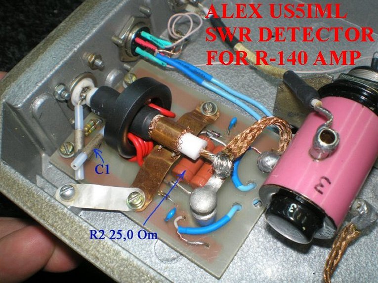
Nota: It is better to select the schematic with one resistor R2 and mid tap at coil, than the other scheme with 2 half values resistors. As it is easier to have EXACTLY the same nb ot turns in coil, than having EXACTLY the same values of the 2 resistors. Any difference in the 2 resistors values would give errors in SWR measurements results.
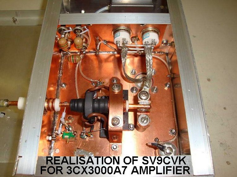
Place the WIDE ground return strip(s), not a single wire, between coaxial line, circuit board and main ground frame, as close as possible to the toroid, to have the best accuracy in POWER measurements over a wide range of frequencies. For SWR measurements ONLY, this is not important, as the ratio FWD/REF is independant of absolute values of detected voltages.
To have perfect balance of the bridge, with the calculated values given by EXCEL sheet, it is important to know the " TRUE " values of the coil(s), resistor R2, and capacitor C1. To know what is the exact Al value of your toroid, coil 5 turns of wire into it, measure with a LC meter, and divide value by 25. A variable C2 capacitor, as shown, is MANDATORY, to compensate for all tolerances in components values, parasitics. During tests, dont hesitate to modify calculated value of C2 (fixed + adjustable value) to obtain the best balance.Tolerances and parasitics management is not an exact science.
Check of coil(s) and capacitor C1 exact values can be made with a LC meter, like the one described in pages " Technical " and proposed by DF1SR (ex DD0SB).
Adapt cross sectional area of wires in toroid to maximum current in R2, do not undersize, 3 Amps by square milimeter is a maximum.
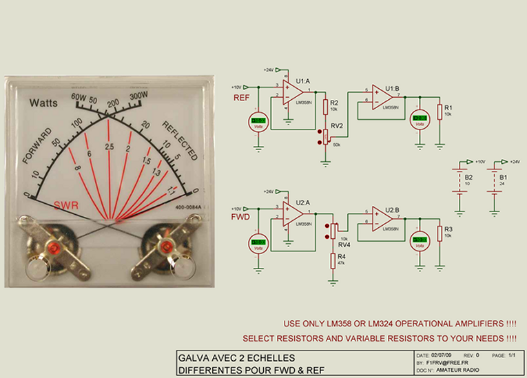
Load on detector diodes is a first order parametre for rectified voltages output. Do not hesitate to use operational amplifiers LM358 or LM324 as buffers (they include GND in common mode range). In this case, with very high impedance detectors load, to avoid too high time constant in SWR readings, reduce, if necessary, the values of decoupling capacitors in FWD & REF outputs (10 nF is OK with operational amplifiers, 100 nF or more without operational amplifiers).

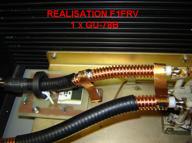
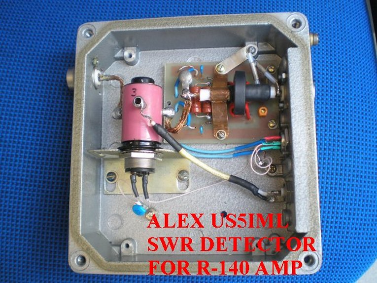
Note the wide ground strap (12 x 0.5 mm) behind toroid

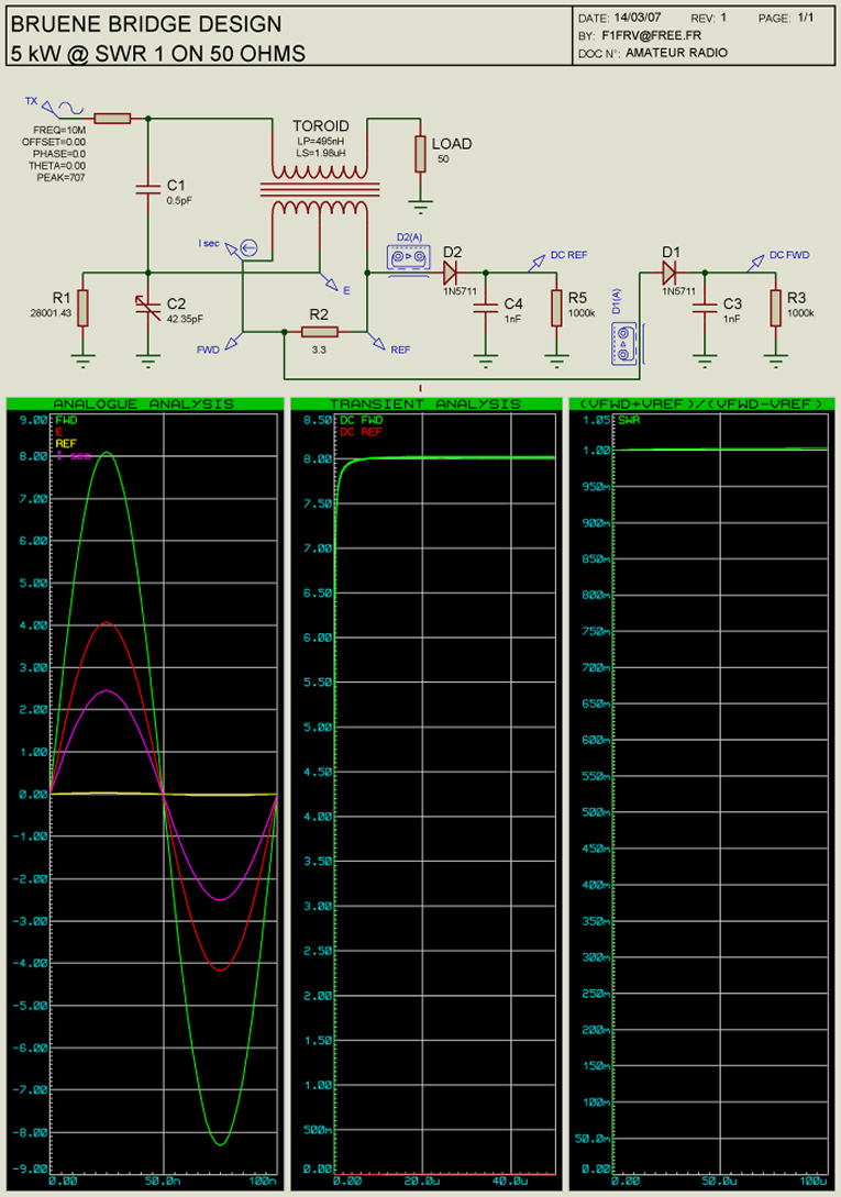
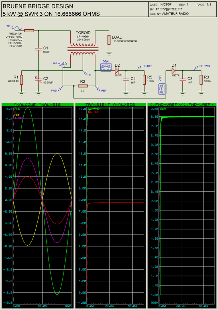
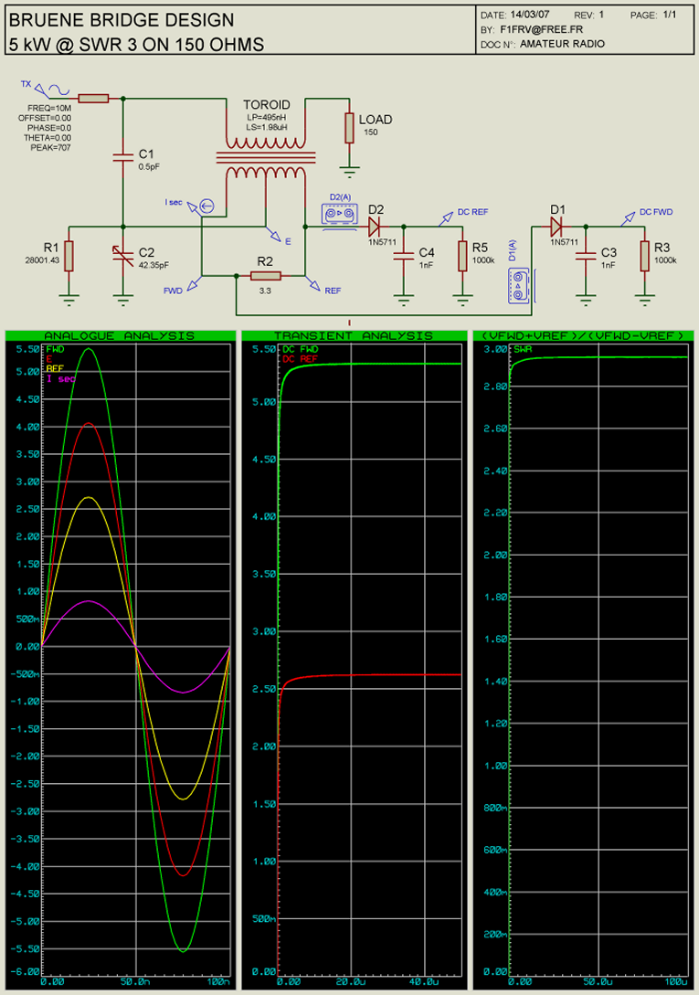
Simulations of the bridge phase & balance
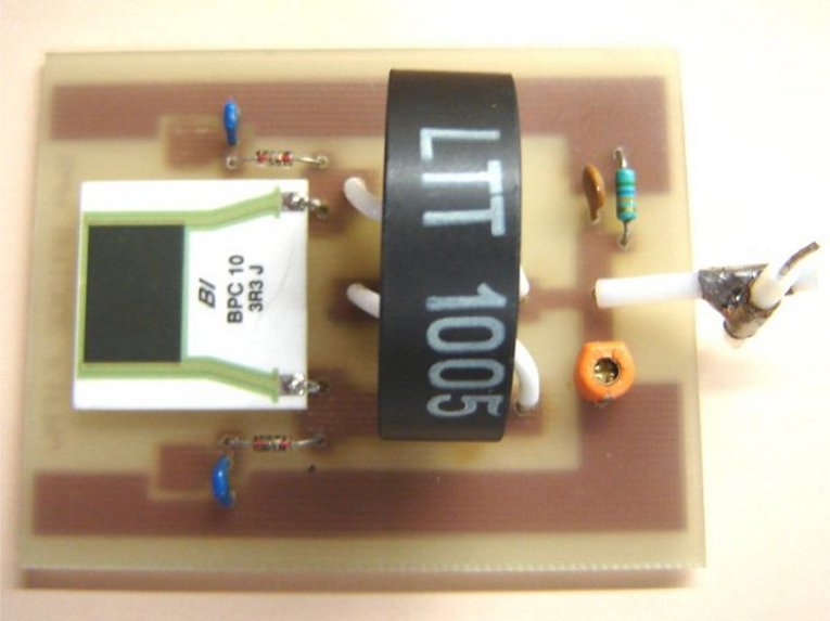
Bridge old revision 3 PCB & components picture


Detail of the 0.5 pF @ 4000 V capacitor ( 2 x 10 mm of copper of RG402 )
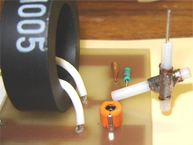
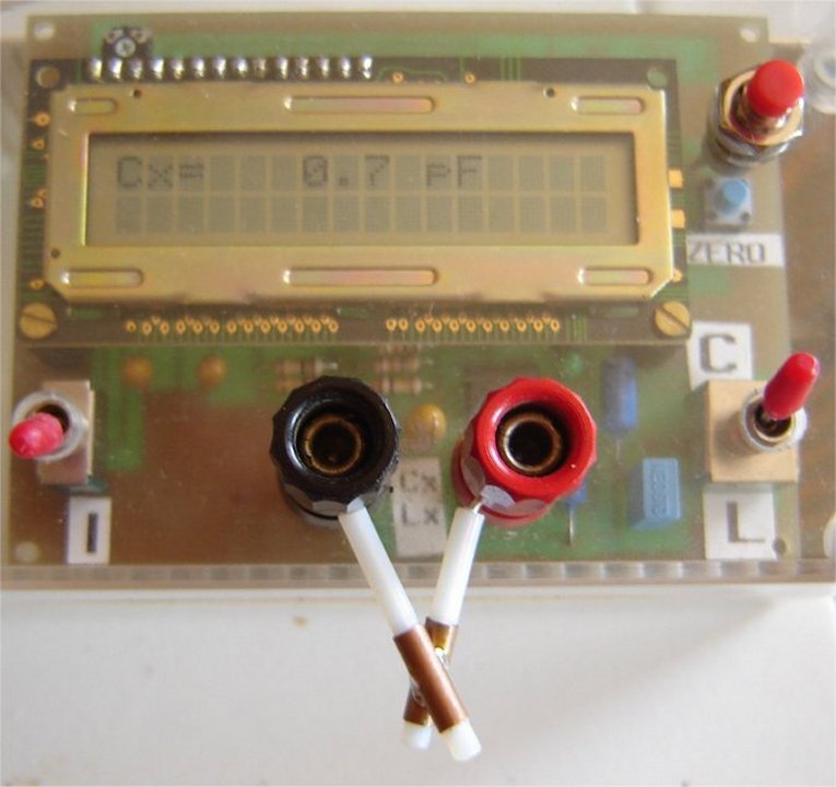
Measurement of a 0.7 pF @ 4000 V capacitor ( 2 x 14 mm of copper of RG402 )
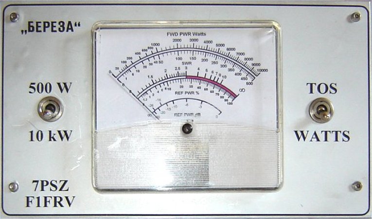
Front plate with meter
Tidak ada komentar:
Posting Komentar